Wymiana / naprawa zamka (mikroswitch, zimne luty) drzwi Passat B5, Golf IV, Audi A3, Skoda Octavia, Fabia, Seat Leon, Toledo itd.
Uwaga opis pochodzi ze strony: www.taligentx.com
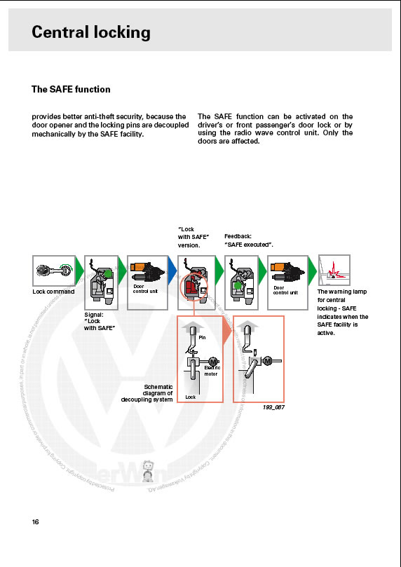
Elekryczne zamki w autach grupy VAG to częste problemy. Jeśli masz problemy z zapalaniem się oświetlenia po otwrciu drzwi lub zamek nie zamyka się na 2 razy (ryglowanie) gdy wciskasz pilota, dioda safe w drzwiach kierowcy nie zawsze zapala się lub zwyczajnie zamki wariują to dobrze trafiłeś. Lokalizujesz tylko które drzwi (diagnostyka vag-błędy lub samemu sprawdzasz po kolei poprawność działania - oświetlenie, dioda, zamykanie na 2 razy z ryglowaniem) i zabierasz się do roboty. W większości przypadków można sobie poradzić bez zakupu nowego zamka, najczęściej pada albo mikroswitch, lub zimne luty na płytce. Switch da się dobrać tylko trzeba dobrze poszukać a zimne luty przelutować. Zdarza się też że reanimacja nie przyniesie skutku, wtedy trzeba szukać nowego zamka, używkę w dobrym stanie można już znaleźć za 70-100 zł.
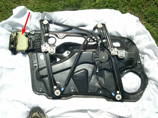
Fotorelacja z demontażu zamka z drzwi przednich na przykładzie VW Passata B5, w innych autach jest bardzo podobnie. troszkę inaczej wygląda to w drzwiach tylnych ( przy wyjmowaniu szyby w przeciwieństwie do przodu, gdzie odkręca się 2 śruby trzymające szybę z tyłu mechanizm trzymający szybę się różni, aby ją wyjąć trzeba wyjąć plastikową zawleczkę blokującą, precyzjna robota, reszta tak samo). Dokładny opis z całej roboty w języku angielskim, lecz można poradzić sobie i bez niego oglądając każdy krok z fotek.

WAŻNE !!!
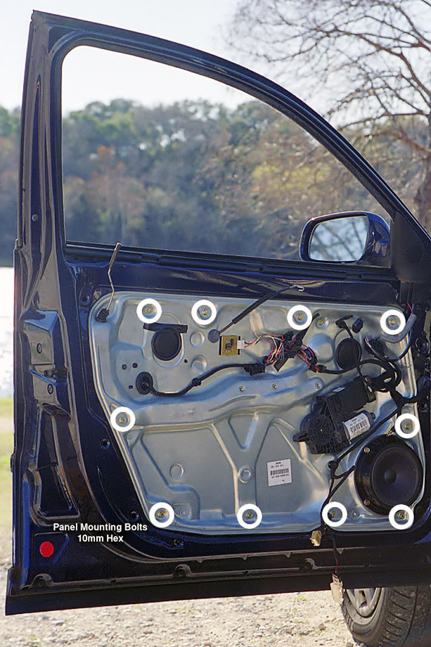
Po odkręceniu wszystkich śrub, blachy nie da rady wyjąć, blokuje ją mechanizm opuszczania razem z szyba, należy wyjąć zaślepki z 2 otworów i opuścić szybę tak, aż pojawią się łapy szyby skręcane śrubami, poluzowujemy te 2 śruby i wyjmujemy szybę. Teraz blachę można odchylić już w wystarczający spsób, aby wyjąć interesujący nas zamek.

Symptoms:
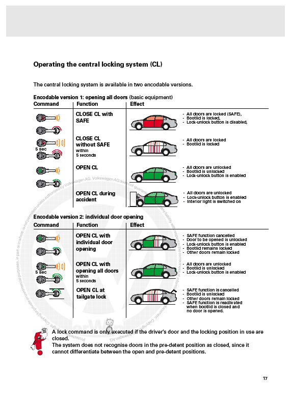
Door(s) fail to respond normally to lock/unlock signals. In several cases, sending a lock signal via remote locks all but one door. Subsequently sending an unlock and second lock signal then locks the problematic door. Also, when the door in question is the driver's side front door with an aftermarket window controller (AlienTech, etc), the controller usually fails to operate as usual.
Problem:
The door locking mechanism - responsible for coordinating the activities of the handles, key, and alarm - is having an electronic malfunction, most likely a cracked solder joint from repeated door opening/closing. This is combined with a poor design layout that stresses internal solder joints if the locking mechanism screws loosen and allows movement of the entire unit in the door.
This, of course, is assuming that the door locks and unlocks mechanically without problem (through the interior handle, exterior handle, and key insertion).
Replacing the part with a new one will be a definite fix, but you may also want to consider popping the unit open and look for any obvious problems - despite appearances the internal parts susceptible to failure are simple to troubleshoot and repair.
Also, considering that you'll be removing the inner door panel to access the locking mechanism, now would be a good time to add some noise dampening material to the metal door skin if you desire. There is a damping panel in place from the factory, and it would be interesting to hear if adding additional material would have a noticeable effect.
Note - always confirm part numbers by looking at the actual part mounted in the car! Mistakes will happen sometime, somewhere.
Part numbers:
| '98-01 | ||
| Driver's front door lock module pre VIN 3B-X-090000 post VIN 3B-X-090001 |
3B1 837 015 E 3B1 837 015 J |
|
Passenger's front door lock module pre VIN 3B-X-090000 post VIN 3B-X-090001 |
3B1 837 016 D 3B1 837 016 R |
|
'01.5-05 |
||
| Driver's front door lock module | 3B1 837 015 AK | |
| Passenger's front door lock module | 3B1 837 016 BH | |
Tools:
- Socket wrench
- 10mm socket
- Torx drivers/bits: T10*, T20, T25
- 12 point star driver/bit (aka triple-square or spline bit): M8
- Soldering iron*
- Solder* (try Kester! Good stuff.)
- Desoldering braid*
- Multimeter*
*Only needed if disassembling the locking mechanism.
Autozone carries a good variety of bits, more so than the other chains I've tried (O'Reilly's, PepBoys, Sears Hardware). You should be able to find the triple square bit in a multipack - buy it, the pack is useful for other work on the car. While you're there, also pick up the large hex driver set - it even includes a 17mm hex driver for removing the auto transmission drain plug. No other store carried the item or had any idea where to obtain it.
Time Required: 1.5-3 hours, depending on individual pace.
Locking Mechanism Removal:
Start by removing the door trim panel.
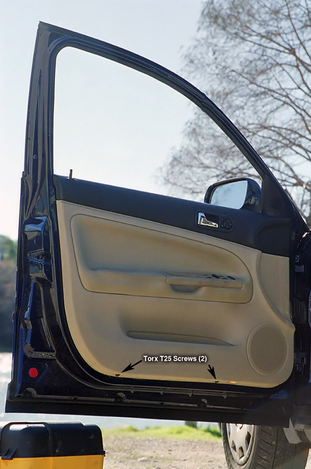
- Begin by lowering the door window glass completely.
- There are two black Torx T25 screws at the bottom of the door - remove them.
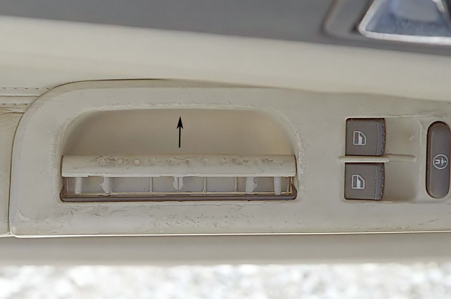
- Use a thin-bladed flathead screwdriver to pry off the inner door handle cover (not the door release handle).
- For the driver side door, you can now pull up on the entire handle/switch assembly as a unit - use moderate force to unclasp the clips holding it in place. Remove the brown wire harness from the handle/switch assembly and set the assembly aside.
- For the drivers side door, there are three bronze color screws anchoring the door trim panel to the rest of the door. The passenger's side door has two of these screws. Use a large philips-head screwdriver to remove these.
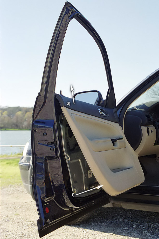
- The rest of the door trim panel is now held in place by snap-in anchors and can be loosened by pulling the trim panel away from the door. Begin with the bottom of the door and give it a good tug to pop out the connectors. Take care not to pull the trim panel far away from the door, as there are several wire/cable connections still in place between the trim panel and door. After the lower portion of the trim panel is separated, pull the entire panel upward to unhinge the panel from the window sill. The trim panel should now be free from the door, with several wires and cables still in place.
- Disconnect the following from the trim panel:
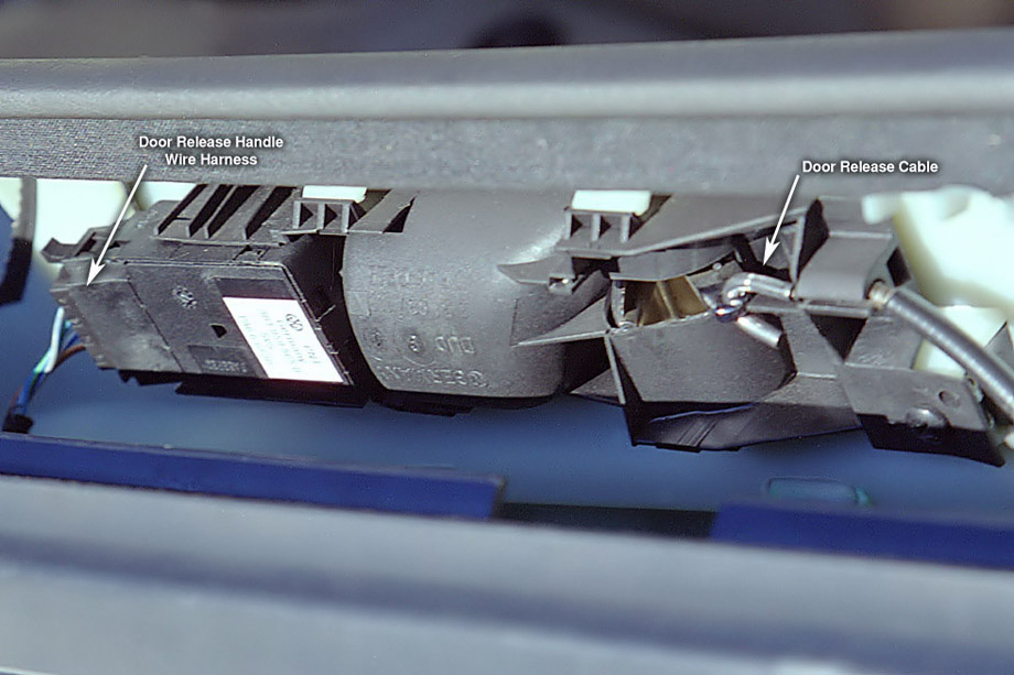
- Wire harness plugged into the door release handle.
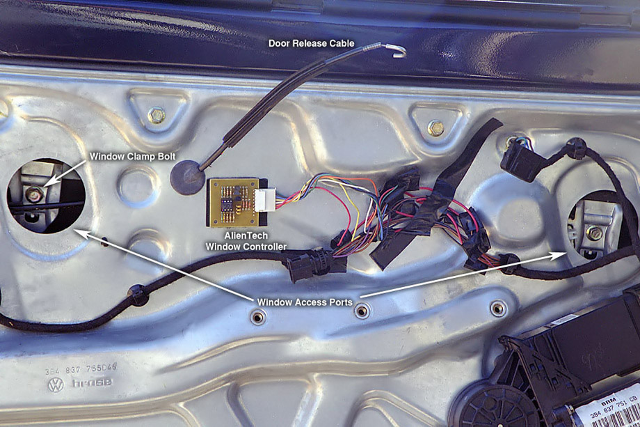
- Door release cable. To remove this, pull the cable insulation away from the hooked end and slide the exposed cable out of the slitted retainer. Release the hooked end.
- Security alarm LED wire connector.
- Bottom door sill lamp - it's easier to pull out the entire wire harness + lamp assembly than to disconnect the wire harness.
- Pull the door trim panel away and set aside.
Next, window glass removal:
- Remove the two large, circular rubber inserts from the metal door panel. If you pry with a screwdriver, take care not to damage the mating surfaces.
- Reconnect the handle/switch assembly to the brown wire harness to allow window control. With the key in the On position (no need to start the engine), roll up the window until the window clamp screws are accessible through the circular cutouts.
- Use a 10mm socket to loosen the clamps holding the window glass in place - it will only take a few turns to loosen the clamps, no need to remove the screws entirely.
- Roll the window down until a third of the window glass is left visible in the window frame.
- Disconnect the handle/switch assembly.
- Remove the window glass. Reach over the top of the door and pull the window glass upwards (towards yourself). As you raise the window glass, angle it towards the hinge side of the door to allow the window glass to clear the window slot. Set the window glass aside.
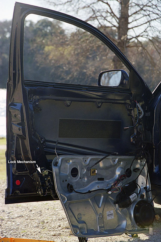
Unhooking the lock mechanism:
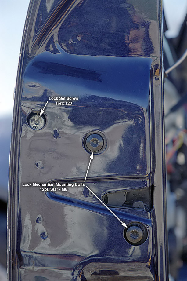
- On the end side of the door, pry off the black plastic cap above the lock mechanism screws. This cap covers the access hole for the lock set screw.
- Use a Torx T20 driver to unscrew the set screw. Unscrew it as far as it will go, then reinsert a few threads to keep the screw from falling out of its mounting.
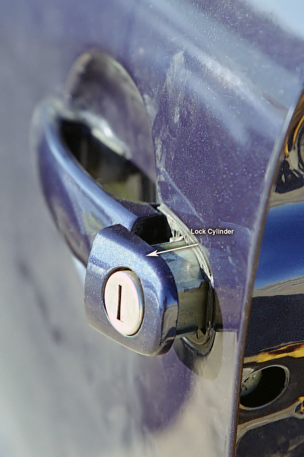
- Pull on the exterior door handle - with the door handle in this position, pull on the lock cylinder. It should slide out without much trouble. Set the lock cylinder aside.
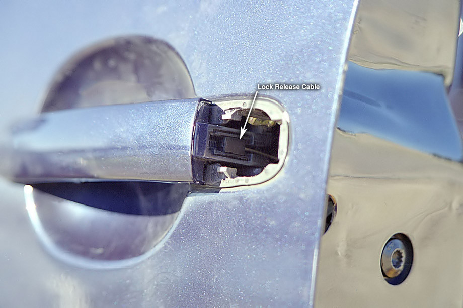
- There is a cable hooked into the side of the exterior door handle. The cable can be positioned at various points along the handle. Note the current position of the cable and release it from the handle.
- Use the M8 12 point star driver to remove the two screws in the door side. On my car, these screws were loose and allowed the lock mechanism to move around, causing solder joint stress - keep reading...
Removing the metal panel:
- Disconnect the various wire harnesses on the metal door panel - don't worry about what goes where - each connector can only fit in one and only one place. Also use a flathead screwdriver to unclip the various snaps holding the wiring to the panel.
- Use the 10mm socket to unscrew the ten hex bolts securing the metal panel to the door frame.
- Pull the panel away from the door frame starting at the edges - if you haven't removed the panel before, the gasket may require a bit of force to pry it away from the frame. Carefully maneuver the entire panel around until the panel is free of the door frame with the lock mechanism and associated wiring attached.
- Remove the wire harness from the lock mechanism and remove it from the metal panel - this will allow you to completely separate the metal panel from the door.
Removing the lock mechanism:
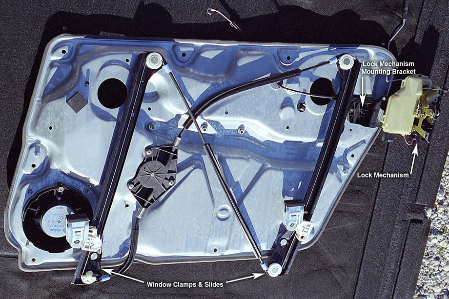
- The lock mechanism is held in place on the metal panel by a plastic bracket with two cylindrical pins keeping the bracket in place. Use a blunt tool to push the pins out from the rear of the panel. My Passat had managed to work the pins loose and dropped them into the door frame, where they've likely lain for months. The bracket had then worked loose of the panel and the entire lock mechanism was free to jostle around in the door. The wiring harness, still being pinned in place, then stressed the electrical connectors internal to the lock mechanism and cracked a solder joint.
- Unhook the door lock pin rod from the lock mechanism.
- Remove the interior door release handle cable. Start by popping the harness out of the mount on the locking mechanism, then unhook the cable.
- Separate the locking mechanism from the panel.
If you are simply replacing the entire mechanism, pop on the replacement and retrace your steps. If you're feeling charitable, contact me - I'd like to take a look at other failed units and see if the problem with mine is common, or if Passat owners can expect a variety of failure modes. If you'd like to attempt repair, read on.
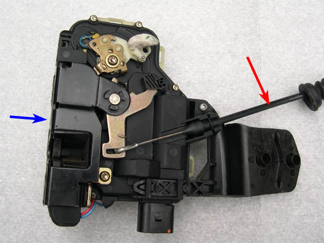
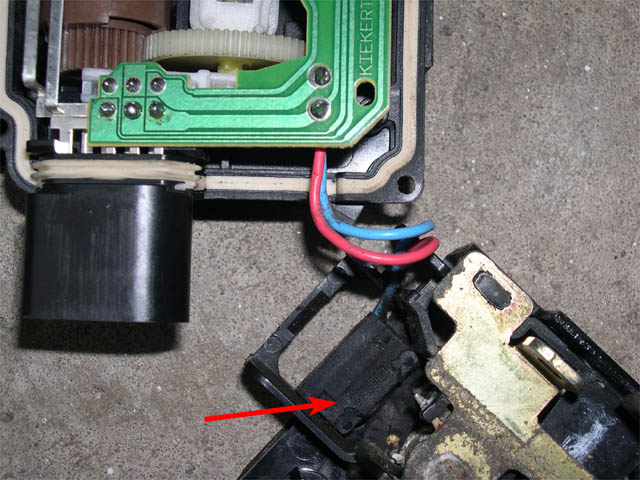
The trouble area of the mechanism is in the electrical connection part of the unit. This is the black & pale yellow plastic section held together by a total of 8 screws and two plastic snaps.
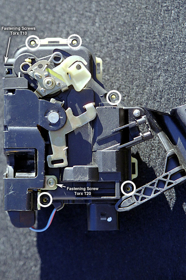
Locking Mechanism Disassembly:
- Use a Torx T10 driver to unscrew the 5 visible Torx screws (four on the face, one on the side).
- Pull the plastic bracket's long clip from the mechanism - there is a sixth screw hidden underneath.
- Use a Torx T20 to remove the large Torx screw.
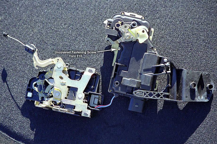
- You should now be able to carefully pull apart the two sections of the mechanism - you'll need to unclip the plastic snaps while pulling the sections away from each other.
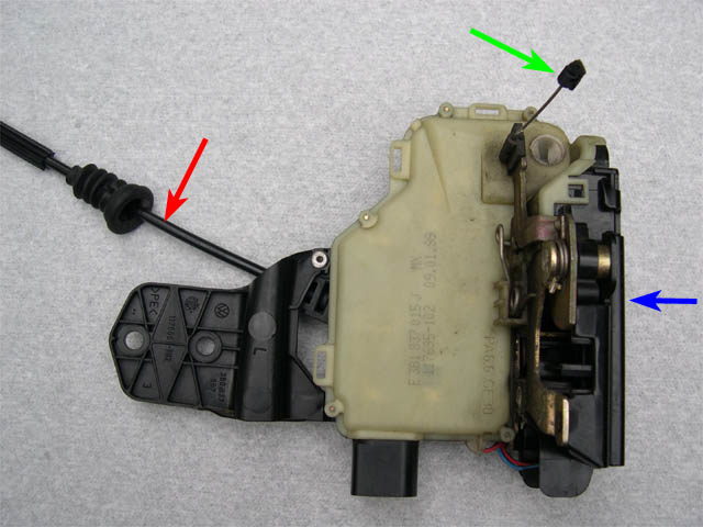
- After pulling these sections away, the last Torx T10 screw will be revealed. Remove it.
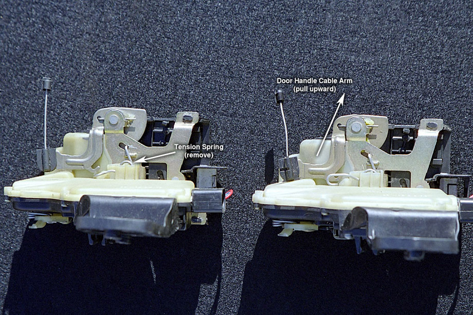
- Flip the mechanism to the yellow plastic side. Pull and remove the spring indicated.
- Pull the metal handle indicated upward to allow separation of the two halves.
- Flip to the black plastic side without allowing the two halves to separate.
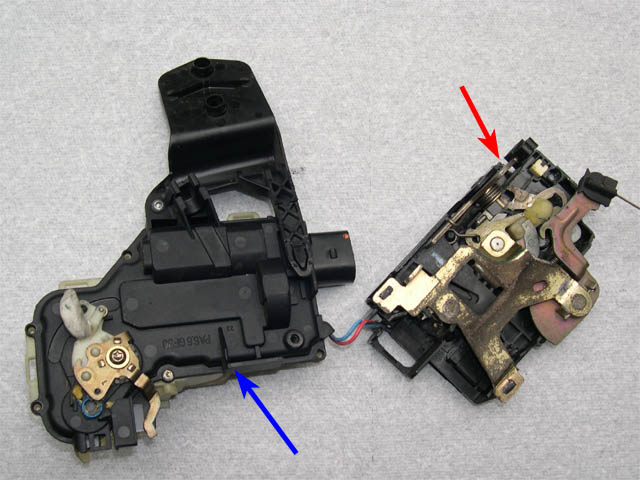
- The internals of the mechanism are mounted on the yellow plastic half - carefully pull up on the black plastic half to reveal the electronics inside.
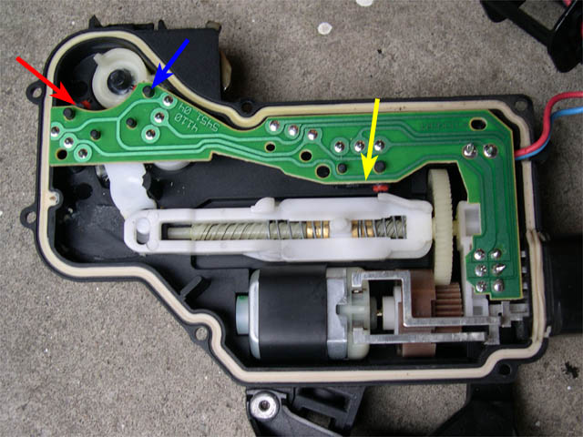
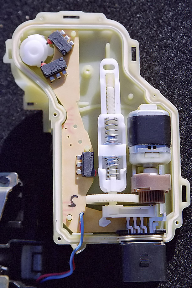
Locking Mechanism Diagnosis:
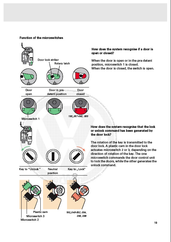
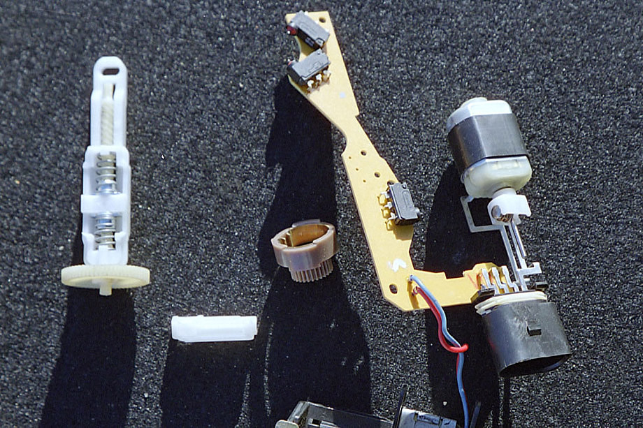
The electronics are straightforward. Two microswitches at the top of the unit detect if the key is moving the lock cylinder to the lock or unlock positions. The microswitch next to the white plastic slide determines the current state of the door lock. The motor actuates electronic locking and unlocking.
Note: Take care not to change the position of the various handles and slides - it's fairly easy to determine how the different switches and handles interact with each other when it's time to put things back together, but it's easier to leave everything in the positions discovered. Also, note the position of the brown gear on the motor shaft to the small white attachment mounted inside. There is an alignment between the notch in the copper track inside the brown gear and a metal cylinder in the white plastic container. Just be sure to reset this relationship during reassembly.
- Pull the white slide from the assembly, along with the white mount holding the shaft of the plastic slide screw and the motor shaft in place. Set aside, without changing the state of the plastic slide and screw.
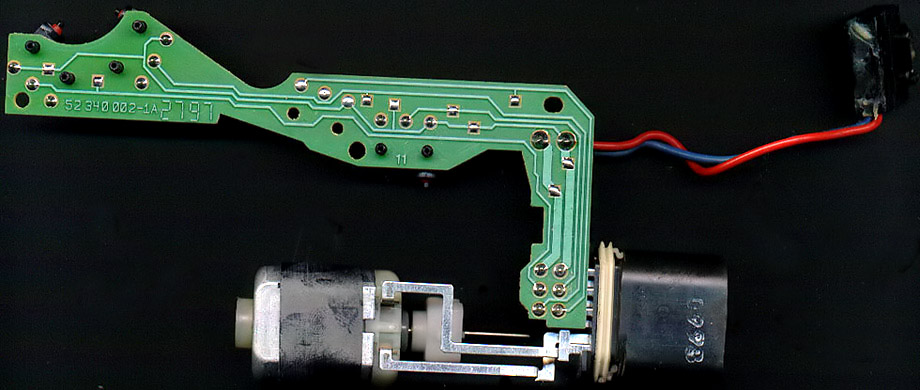
- Pull the circuit board and motor from the yellow plastic half and flip upside down.
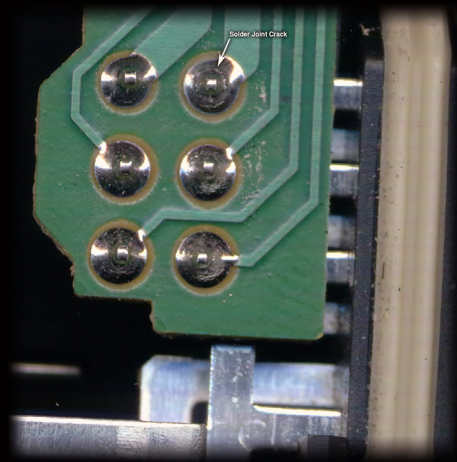
Troubleshooting:
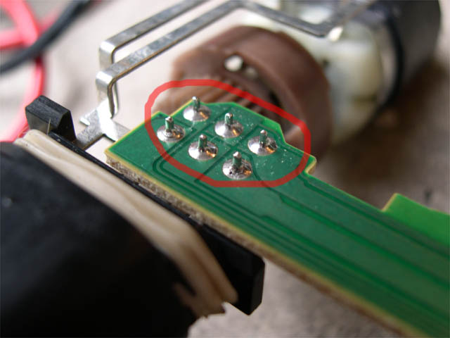
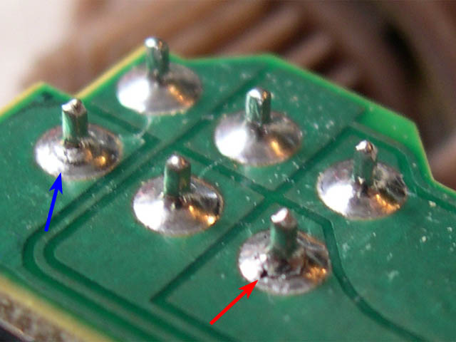
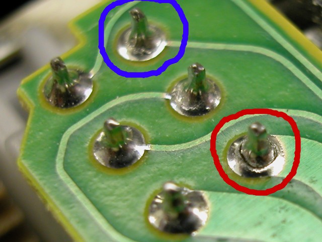
- Start by examining the solder joints where the wire harness connectors meet the printed circuit board (PCB). I had a cracked joint at pin 7.
- Move on and visually inspect the solder joints for the three microswitches.
- Use a multimeter and test each of the microswitches at the solder joints for correct operation. Usually, only two of the three contacts are used - when the switch is depressed, the two used contacts should have 0 or near 0 resistance (or if your multimeter has continuity checking, it should give a tone). Though usually only the trunk microswitch has a tendency to go bad, this could have occurred here as well. If a switch is bad, you'll need to replace it - there should be a part number somewhere for the switch, if all else fails you can always order a trunk microswitch and mount that.
- If the switches are good, it's probably a solder joint problem. Heat up the soldering iron and use the desoldering braid to remove all of the solder from every joint in use on the board. Work in sections - remove solder from a few pins, and then resolder the same connections. Removing solder from all of the joints at once from a component will cause it to fall off the board and leave you to realign it. Not difficult, but easy to avoid anyway.
- The red and blue wires connecting to the other section of the unit are used for a fourth microswitch - it isn't necessary to remove the microswitch from its mounting clip, but do test it as with the others.
Hopefully you've just done something that fixed the problem. Reassemble in the reverse order and see if your door (and wallet) is happy!
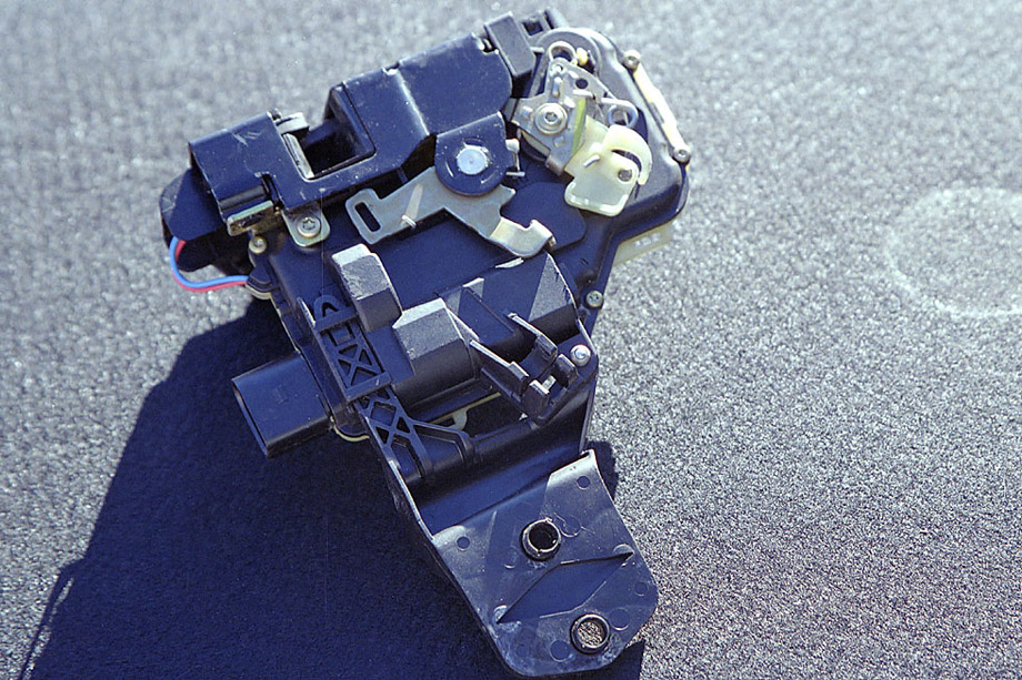
Na koniec jeszcze parę fotek obrazujących rozłożony zamek